This article describes part of the build of a Sharp-Stewart 0-4-2T engine from the Clogher Valley Railway. This was a 3ft gauge railway in rural Northern Ireland, that ran mostly along public roads, and hence combined tramway-style skirted engines pulling regular carriages and goods wagons. Unfortunately I’m not able to find a copyright-free image of the locomotive on the internet to reproduce here, but an excellent gallery is available at https://transportsofdelight.smugmug.com/RAILWAYS/IRISH-RAILWAYS/CLOGHER-VALLEY-RAILWAY/
The build is still on-going (i.e. it needs me to get around to finishing it). However this article mainly looks at the photo-etched brass shell, which is largely complete. I also quickly touch on some 3D printed metal parts. I’m deliberately not covering the laser-cut steel frames and running gear.
CAD design
I used OnShape – a free, online CAD tool – to design the engine. The trade-off for being free is that your designs are publicly available to anyone who knows how to search for them.
I started by finding some reliable looking sources for the key dimensions (overall length, track gauge, wheel separations) and some side-on and front-on photos, and from these it was possible to come up with decent guesses for the rest of the measurements. Most of this was fairly approximate, and by eye. When I picked the project I made sure that it was a suitable size that I could use a Roundhouse boiler – there’s a bit of leeway here since the shell of the engine hides the exact size of the boiler.
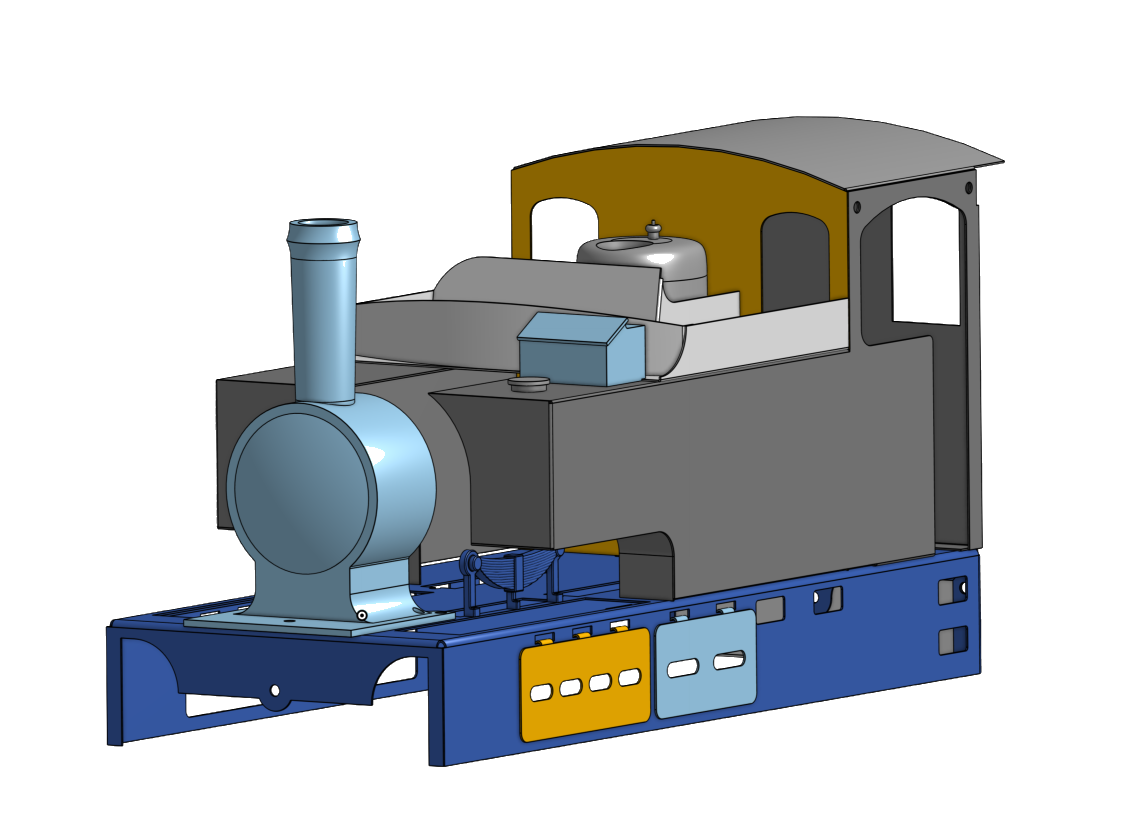
The “sheet metal tool” (something similar will exist in most major CAD programs) is ideal for photo-etched brass. Here you first design a solid block of the correct shape, and then convert that to a shell. For each individual edge you pick whether to make a fold or a break. Once an object is in sheet-metal form it’s possible to make small modifications, for example holes and cut-outs in individual faces.
It’s worth taking advantage of symmetry wherever possible: I found it easiest to do this at the “solid block” stage, which should be constructed using the reflection constraints rather than manually replicated for both sides of the engine. This saves effort when tweaking dimensions to get it to look right – if you’ve built it right you should only need to tweak a dimension once.
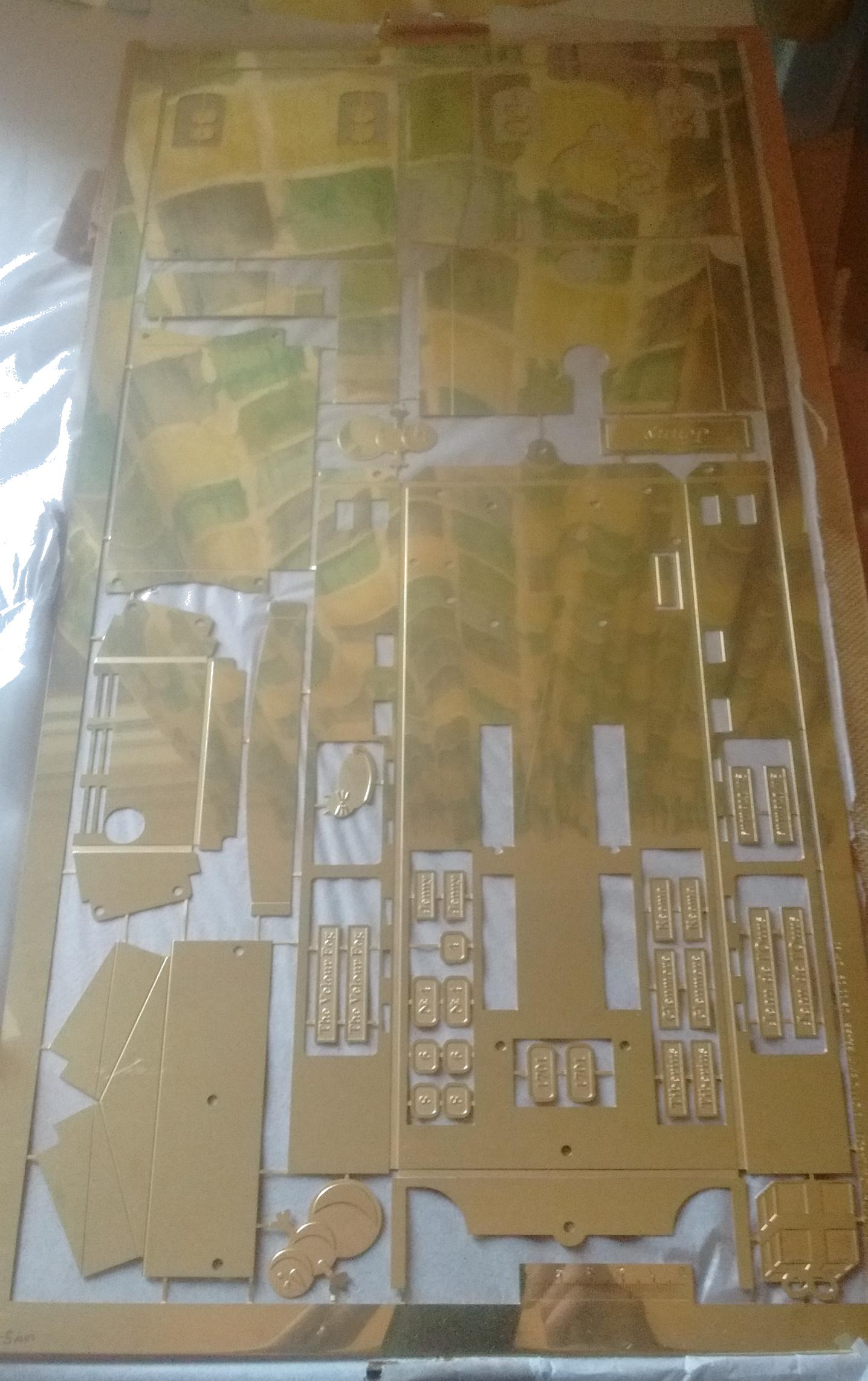
I designed the brass shell as a number of parts. The skirting was done as one large piece. The tanks and the cab sides were done as two almost identical mirror images (there was a small cut-out on one side for the reverser control rod). Then some smaller pieces were needed such as the cab roof, the front panel of the cab, the cow-catcher at the back (the prototype ran in rural Ireland after all), the underside of the tanks, and the access panels on the skirting. The coal bunker that sits atop the tanks is constructed from a number of small pieces.
Preparing drawings for the photo-etchers
This step is unfortunately pretty tedious.
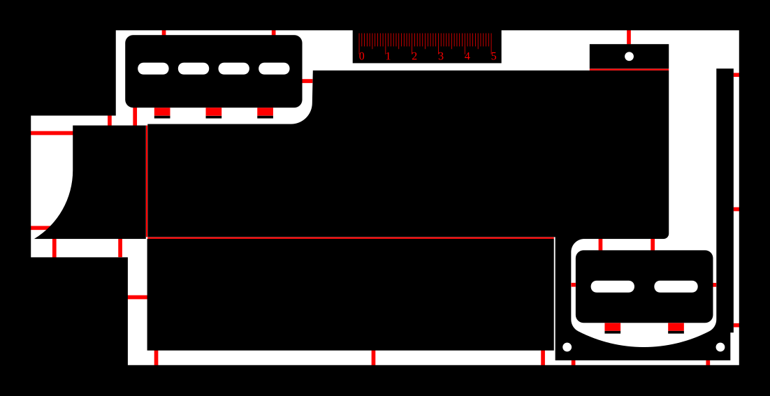
Typically photo-etchers need a drawing consisting of block colours – black for unetched, white for etched-through, and red/blue for half-etched (with the colour designating which side is etched). OnShape can provide nice line drawings of your flattened sheet metal shell. It’s worth tweaking the settings here so that everything is drawn as solid lines and only the “fold regions” (the bits that should be thinned) but not the central fold lines are shown.
I then opened this exported image in Inkscape, and painstakingly converted the line drawing to a “filled” shape drawing by turning on “edit paths by nodes”, and selecting the two overlapping end nodes from each line-segment and using “join selected nodes”. When this is finished it’s possible to set a fill colour for each region and put them over a black background. It’s best to keep all drawings, including the final version sent to the photo-etchers, as “vector” drawings (defined by lines and curves), to avoid losing detail.
Careful arranging of individual pieces is needed to ensure efficient use of the space (this saves some money!). Small half-etched tags between pieces ensure that no pieces are left floating.

Assembly
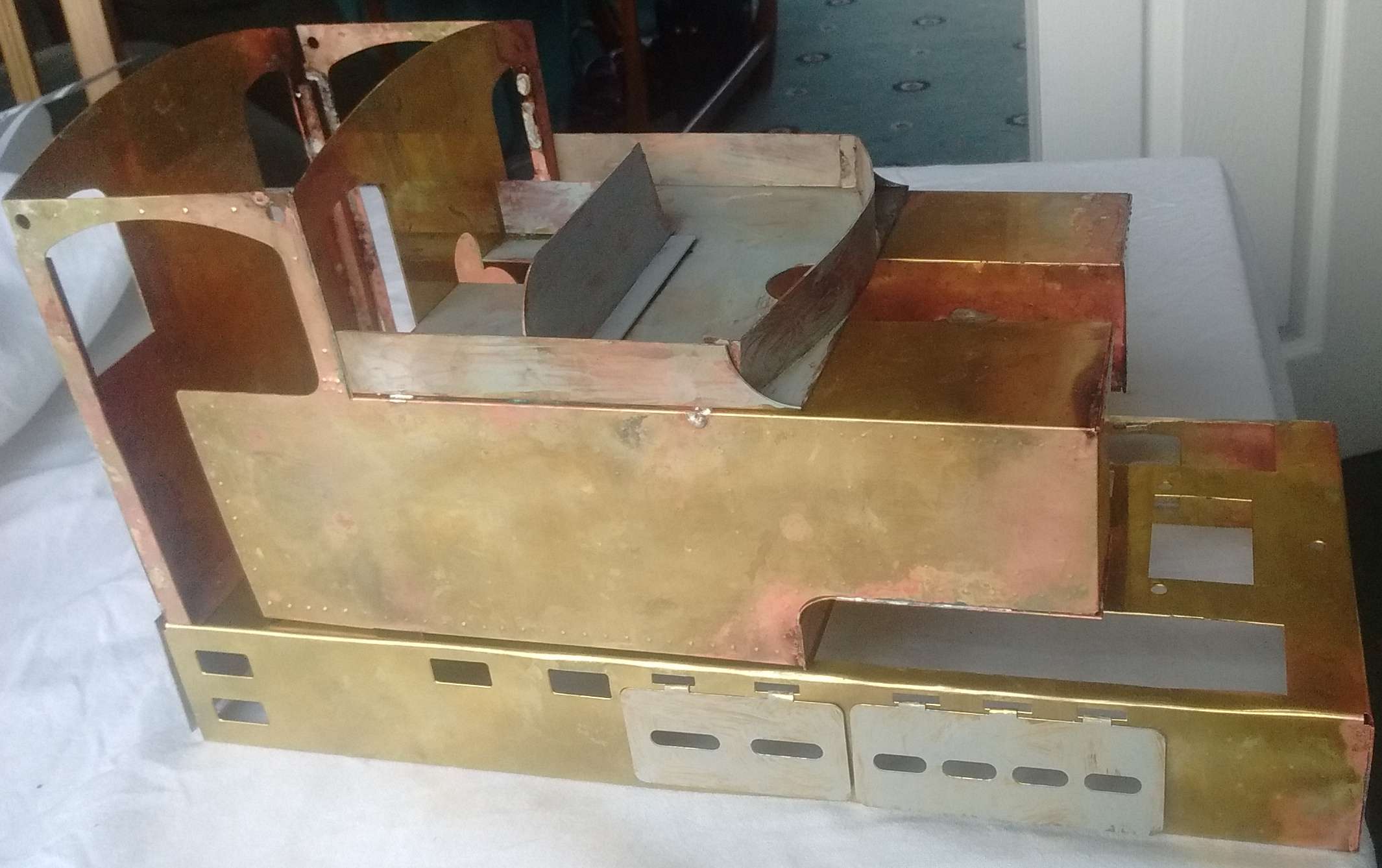
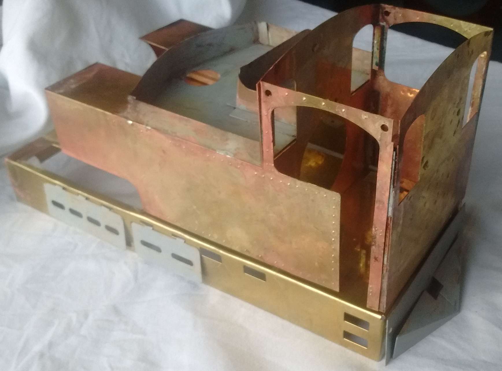
I ordered the etched brass (0.5mm thick) from a Scottish company called PPD, and am pretty happy with the quality of the results. In principle it should be possible to do the etching as a DIY process, and while my degree(s) in Chemistry says that I should be capable, in reality it’s been a long time since I handled “real” chemicals, so I decided to avoid that.
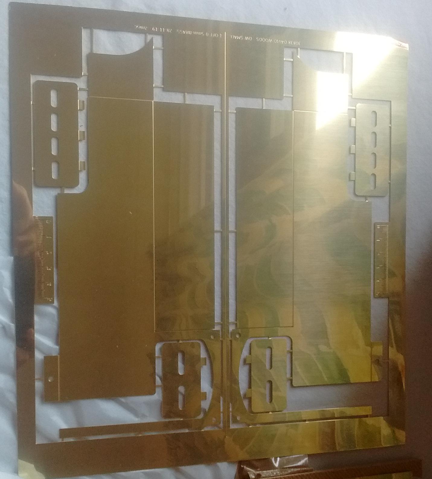
It was then a case of cutting out the individual parts and folding along the bend-lines. The one part where this was slightly unsatisfactory was on the skirting, where some of the thinner edges didn’t fold as cleanly as I’d have liked. I think the trick is probably ensure that the brass either side of the fold is well-clamped and that the whole bend is done in one go. At this stage I added rivet detail with a rivet embosser tool.
Soldering of the tank-cab assembly was done in the garden, with a small propane blow-torch, using 3mm cross-section brass bar inside the edges to help make some of the joins. This worked fine, although arguably building tabs to solder along would have been better.
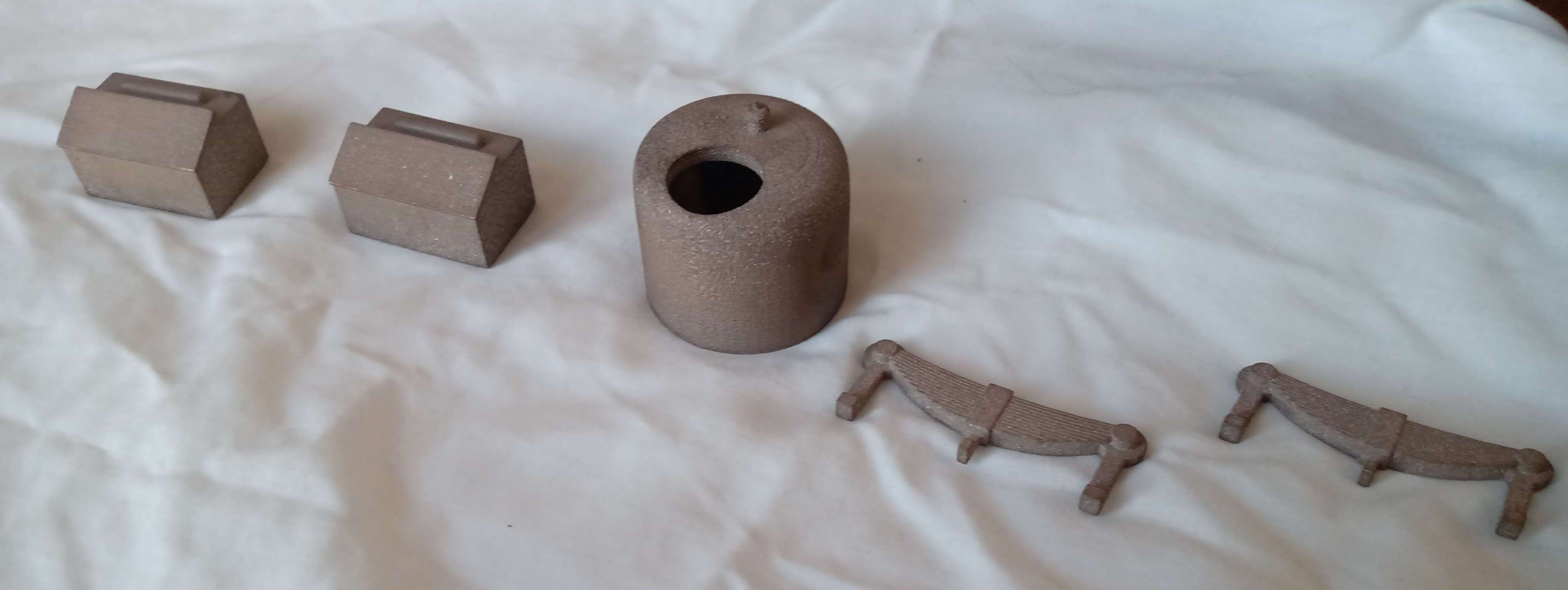
3D printed metal
In addition to the sheet brass body, I also used some 3D printed metal decorative parts: a couple of sandboxes, a couple of fake springs and a whistle/safety-valve dome. There are a number of options of 3D printed metal. The option I chose (largely because it’s the cheapest) is binder jetting, where a steel/bronze mixture is printed as a “damp sandcastle”, and then solidified into a solid lump by melting the bronze. As received the parts were somewhat rough (I chose not to have them polished though) but came out as I’d hoped. For price reasons it’s worth making the shapes as hollow as possible, paying attention to minimum wall thicknesses of course. There are a number of companies that perform this service and their pricing was all very similar. I used “Sculpteo”, and am happy with the results (they even shipped some complimentary beer). They are based in France though, so the cost of importing from them may have risen since I ordered the parts.