Background
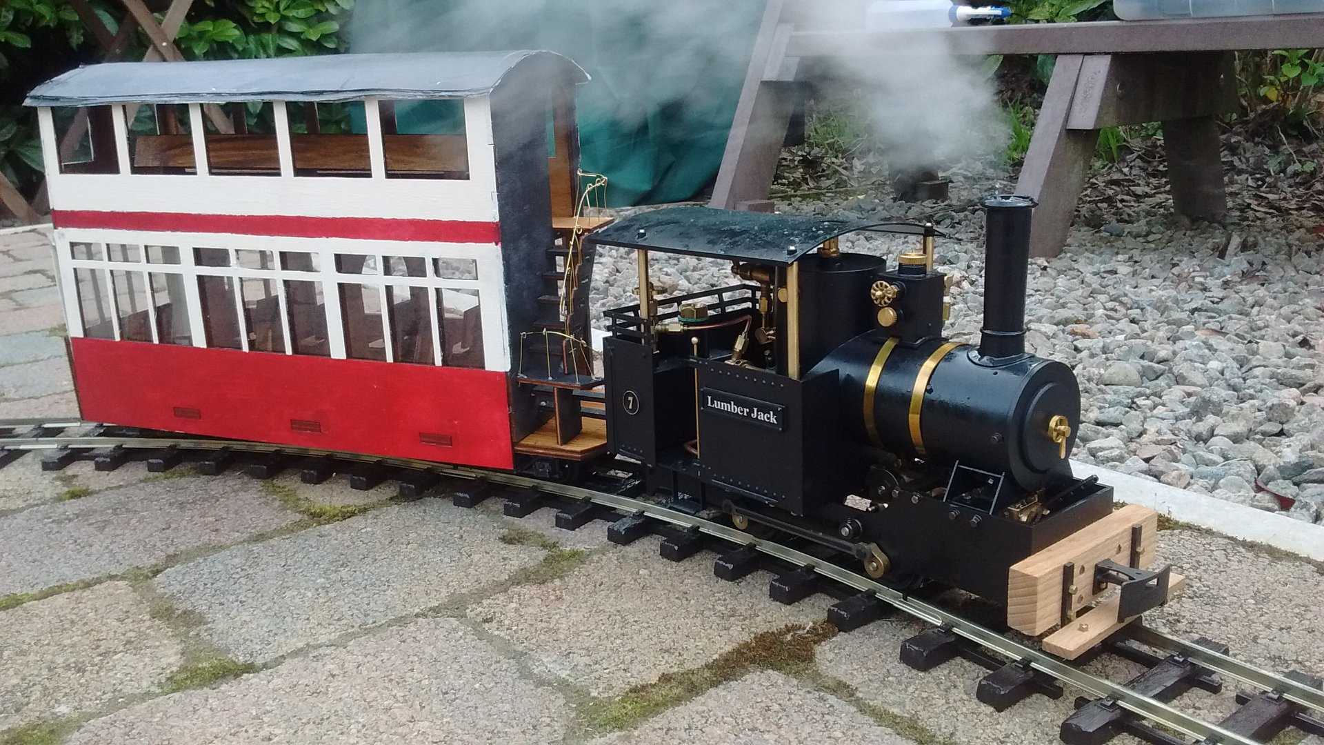
I had not particularly planned to make a tram carriage – I’m not the biggest fan of steam tram engines (to my mind the design tends to hide all the interesting mechanics and they look a bit “boxy”). However, I got distracted while considering a different rolling-stock project that remains as yet unmade. I’d recently bought a Regner Lumberjack which to my mind looks a little like a tram engine, is quite a tall engine (so lends itself to some tall rolling-stock), and which seemed like it might fit a double-decker tram car reasonably well.
The design is mostly “freelance”. I worked from some images from the Birmingham tram system to get a sense of the rough proportion, but scaled the dimensions for the twin aims of a) looking reasonable next to a Lumberjack and b) keeping the floor to ceiling heights somewhat practical for a 16mm scale person (104 mm or 6.5 scale feet for the ground floor and 95mm or just over 6 scale feet for the first floor). I also squared off the steps at the back for simplicity.
.jpg)
Designing the tram
The design was created from the start with a view to building it out of laser-cut plywood as a way of having a design of my own creation, but not being dependent on my slightly shaky woodworking skills. I created rough models of the Lumberjack (for comparison) and the Swift Sixteen bogies I planned to use and set to work building it. The design used 3mm thick plywood, except for the bottom which was 6mm and constructed from two pieces glued together.
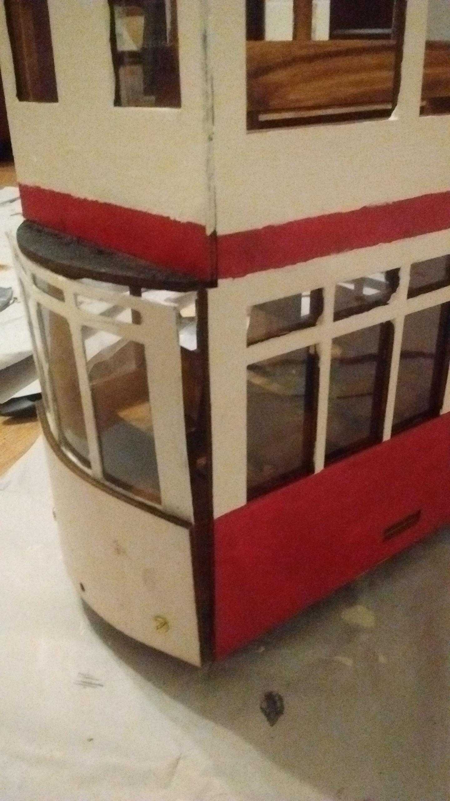
One slightly tricky aspect was creating a curved front: I decided to make the lower panel from plywood, bend with heat and water. The window-frame above was to be made from thin cardboard on the basis that the small frames would be too fragile to bend in plywood.
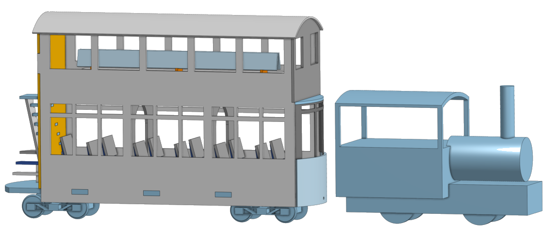
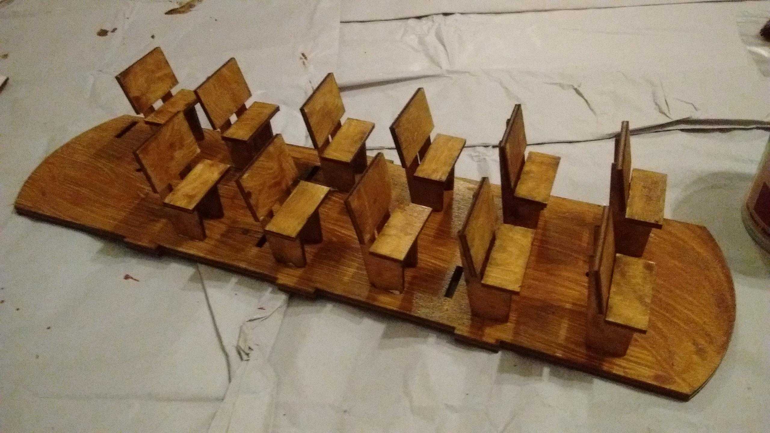
One of the last parts of the design to be finalized was the seating. There was a fine balance to be struck between leaving the seat size and the usable space size so that they appeared practical, and the 3 internal compartment design I’d already chosen for the ground floor. On the upper floor I used long benches running the length of the compartment partly for simplicity and partly to create a little distinction between the two floors.
Notes on CAD
I used an online service called “Onshape”. It is free for personal use, provided you don’t mind your files being publicly available. Like most of the larger CAD packages it uses an approach called “parametric modelling” – the file takes the form of a list of instructions e.g. “start with a drawing”, “extrude the drawing to be 3mm thick”, “create another drawing on one of the object faces”, “remove material from the other drawing”. It is possible to go back and modify each one of those steps, or insert another step, and the model will rebuild itself following the new instructions. I highly recommend using a package with this parametric approach (and thus avoid things like “Sketchup” without it).
For this model I started with a drawing of the ground floor board and extruded it to 3mm. I made heavy use of “constraints” – the edges of the two sides were constrained to be in line with the base, the size of the tabs constrained to be the same as the material thickness, the windows were all constrained to be equal sizes, lines of symmetry used wherever possible. Doing so allows you to easily tweak your model as you go. For example, I could make the base longer and everything else would magically adjust to match.
With laser-cutting in mind, the design was created as an assembly of flat components with the necessary structural slots and tabs designed in from the start. An alternative approach (which I think makes more sense for etched brass models) is to model a solid block, and then convert that to a hollow “sheet metal” design, picking which edges to fold.
The final stage was to convert the design into a format that the laser-cutting service can use. Most metal laser-cutters accept DXF files directly from the CAD program, which is ideal. However, services doing wood-cutting seem targeted at the artistic market rather than the engineering market and so require a PDF file with specific line thicknesses and colours to drive the cutter. OnShape lets you create engineering drawings (no need to add dimensions since there is no-one cutting them manually!) and then export them as PDFs. I then used Inkscape to tweak the drawings to match the format required by the laser-cutting service and to try to save a bit of cutting time by having shared edges between parts.


Building
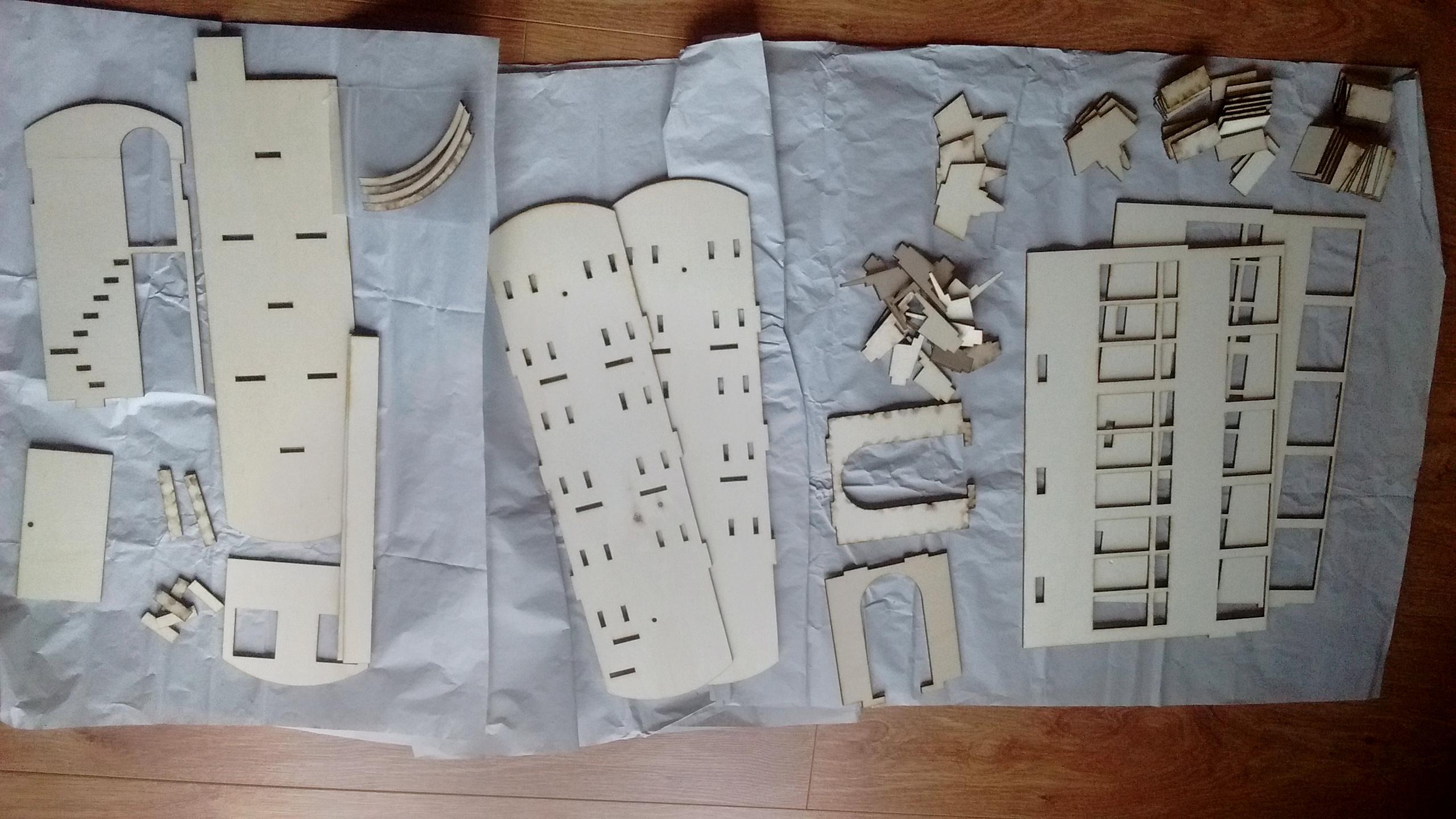
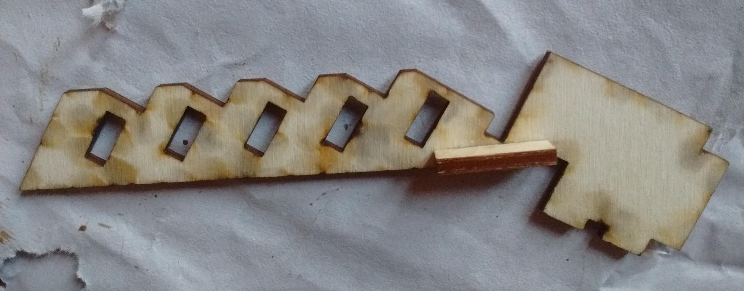
I used an online service called “RazorLab” and was generally pretty happy with the results. There’s no shortage of places that will laser-cut wood though, so do shop around. My first delivery was missing a few parts, but they quickly sorted this. There was a thin neck in the stair support that didn’t survive being posted. In hindsight it was not the most sensible structure and an improved version of the design (which I’m not planning to produce) would avoid it. However, it was readily glued back together and discreetly reinforced.
I’d built the design with various slots to allow the pieces to fit together. However, when assembling it I discovered that the slots were about 0.6mm too wide, presumably due to width of the laser beam. I was expecting and relying on this happening to an extent, having made the design with the slots the exact same size as their matching tabs. Even so, the there was more wiggle-room than I’d hoped. For this model I used thin cardboard shims to fill in the space, but the extra distance is something I will try to account for in future.
Before starting on the assembly the first thing to do was “paint your wagon”, especially the inside surfaces which would be difficult to reach once the tall outer sidewalls were on. The inside was painted with wood-stain, the sides in a red and (light) cream livery, and the back wall, steps and underside in black. I was not particularly happy with the sharpness of the red/cream join – I had not attempted a two-colour livery before and it turns out that masking tape is not as good at masking as I’d imagined.
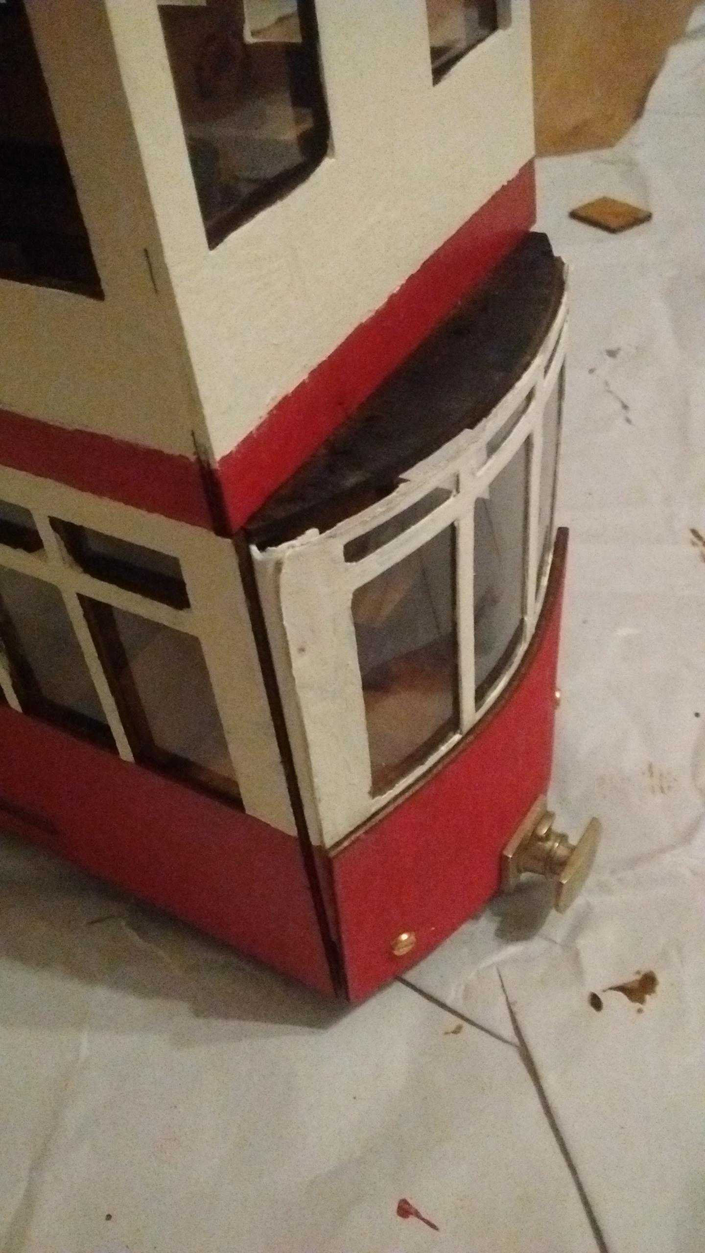
One deviation from my original design was in affixing the curved front. Rather than gluing it I chose to screw it in instead, partly because it seemed a more practical way of bending the panel and partly because I wanted the panel to be removable so I could have some access to make repairs internally if needed – for example to be able to remove the bogies. I drilled a couple of holes into the lower floor in the plane of the floor. Then I drilled holes downwards to intercept the horizontal ones in order to insert a nut. I could then screw into the nut and tighten to hold the curved front panel.
The bulk of the building was straightforward and quick; everything slotted together as planned with glue-drying time being the main hold-up. I was pleased the design worked and required no major changes to be buildable – my approach of leaving all the hard work to the laser-cutter was basically successful.
As a decorative touch I added a handrail to the steps at the rear, constructed out of 0.5mm diameter brass wire. The supports were glued into suitable holes in the steps, while the handrail itself was just hooked onto loops in the supports – soldering the handrail and supports together seemed difficult: either it would be hard to get the positioning right, or (if done in place) it would be easy to set fire to the wood. Although it doesn’t pass detailed inspection from a distance the effect looks good.
Finally the roof was glued to the top, constructed out of the most readily available form of cardboard sheet: cereal packet. I still haven’t quite got the hang of gluing roofs, and this build was no exception.
Nitpicking and conclusions
On the first run the tram turned out to be very unstable. Compared to some slightly smaller commercial kits it felt quite light (at about 400g when I weighed it). I bought a meter length of 30×4 mm deep steel bar and cut off a couple of 20 cm pieces to stick on the bottom. In hindsight this was a very labour-intensive way of adding weight, but it did solve the stability problem.
The project was largely successful – I constructed a fairly unique piece of rolling-stock, it runs, looks pretty similar to what I imagined, and seems like it should be pretty robust. However there are some minor imperfections. For the most part these are barely noticeable so I’ll draw attention to them here in great detail.
First, the upper half of the model isn’t quite square (thus there are some gaps between the upper floor and the walls). This was much more obvious before the roof went on. The culprit is probably that there are too few tabs to force alignment of between the upper floor and the walls: tabs and slots create alignment between the lower floor and the walls, the lower floor and the internal supports, and between the upper floor and the internal supports. I suspect some tabs and slots between the upper floor and the walls would have fixed this.
Second the curved front wall does not fit seamlessly. When I first mounted it there were fairly significant gaps, especially on the top half of windows which are not held directly in place. I solved this by adding small cardboard wings to fill in the gaps. I think the curved wall was the right design decision (a flat version did not look right in the CAD renderings), however curved surfaces and laser-cutting wood do not go together too easily.
Finally, the alignment tabs are a little too visible on the outside (even after painting). Commercial kits usually solve this by using double-layered walls: an inner layer with alignment holes and an outer layer to cover them. Whether this would have been worth the extra material and cutting costs for this project is debatable.
In terms of cost, the tram ended up being similar to most of the commercial kits available (of the order of £100). My model is relatively large although not overly detailed (both of which affect laser-cutting costs). There are doubtless some savings from laser-cutting a model in bulk, but equally the cost here does not account for my time. The advantage of DIY laser-cutting looks to be the ability to make something unique and otherwise unavailable rather than a cost-saving exercise.